Nexelia Academy · Official Revision Notes
Complete A-Level revision notes · 6 chapters
This chapter introduces projectile motion, analyzing objects moving under gravity by separating their motion into independent horizontal and vertical components. It covers calculations for key parameters like maximum height, time of flight, and range, and demonstrates both component-wise and vector approaches to solving problems.
projectiles — Objects moving through the air under the action of only one force, the force of gravity.
Key modelling assumptions for projectiles include treating them as particles, assuming they are not powered, and neglecting air resistance. This simplifies the motion to constant acceleration vertically and constant velocity horizontally. A thrown ball, a shot arrow, or a cannonball fired from a cannon are all examples of projectiles.
trajectory — The path followed by every drop of water in a water jet, or any projectile.
For objects moving through the air under gravity, this path is typically a parabola, assuming certain modelling assumptions are met. Understanding the trajectory allows prediction of a projectile's position at any given time. Imagine the arc a basketball makes when shot towards the hoop; that arc is its trajectory.
velocity — The rate of change of displacement, a vector quantity with both magnitude (speed) and direction.
In projectile motion, velocity has both horizontal and vertical components. The horizontal component is constant, while the vertical component changes due to gravity. If you're driving a car, your speed is how fast you're going, but your velocity also includes the direction you're heading.
initial velocity — The velocity of a projectile at the moment it begins its motion.
This velocity is typically resolved into horizontal and vertical components, which are then used in the equations of motion. The angle of projection is crucial for determining these components. It's the 'kick-off' speed and direction for the projectile's journey.
acceleration of the projectile — The constant acceleration of a projectile, which is g m s⁻² vertically downwards.
This acceleration is due to the force of gravity and is constant in magnitude and direction. There is no horizontal acceleration under the standard modelling assumptions. It's like a car constantly braking downwards, but with no engine or steering input horizontally.
horizontal velocity — The component of the projectile's velocity in the horizontal direction.
Under the modelling assumption of no air resistance, the horizontal velocity remains constant throughout the projectile's flight because there is no horizontal force acting on it. Imagine a car on cruise control on a perfectly flat road; its speed across the ground remains steady.
vertical velocity — The component of the projectile's velocity in the vertical direction.
This component changes due to the constant downward acceleration of gravity. It decreases as the projectile rises, becomes zero at the maximum height, and then increases in the downward direction. It's like a ball thrown straight up, slowing down, stopping at the peak, and then speeding up as it falls.
Horizontal velocity component
Constant throughout flight (assuming no air resistance).
Vertical velocity component
Positive y-axis upwards. g is positive value.
Horizontal displacement
From origin (0,0).
Vertical displacement
From origin (0,0), positive y-axis upwards. g is positive value.
To simplify the analysis of projectile motion, several key assumptions are made. The object is treated as a particle, meaning its size and rotational effects are ignored. It is assumed to be unpowered, so no internal forces are propelling it. Crucially, air resistance is neglected, allowing for constant horizontal velocity. Finally, the acceleration due to gravity (g) is considered constant and acts vertically downwards.
Students often think air resistance is negligible in all projectile motion scenarios, but it significantly affects real-world trajectories. Students often think a rocket is a projectile throughout its flight, but actually it's only a projectile after its engines stop and it's no longer powered.
Be prepared to state and justify the modelling assumptions for projectile motion when answering theoretical questions.
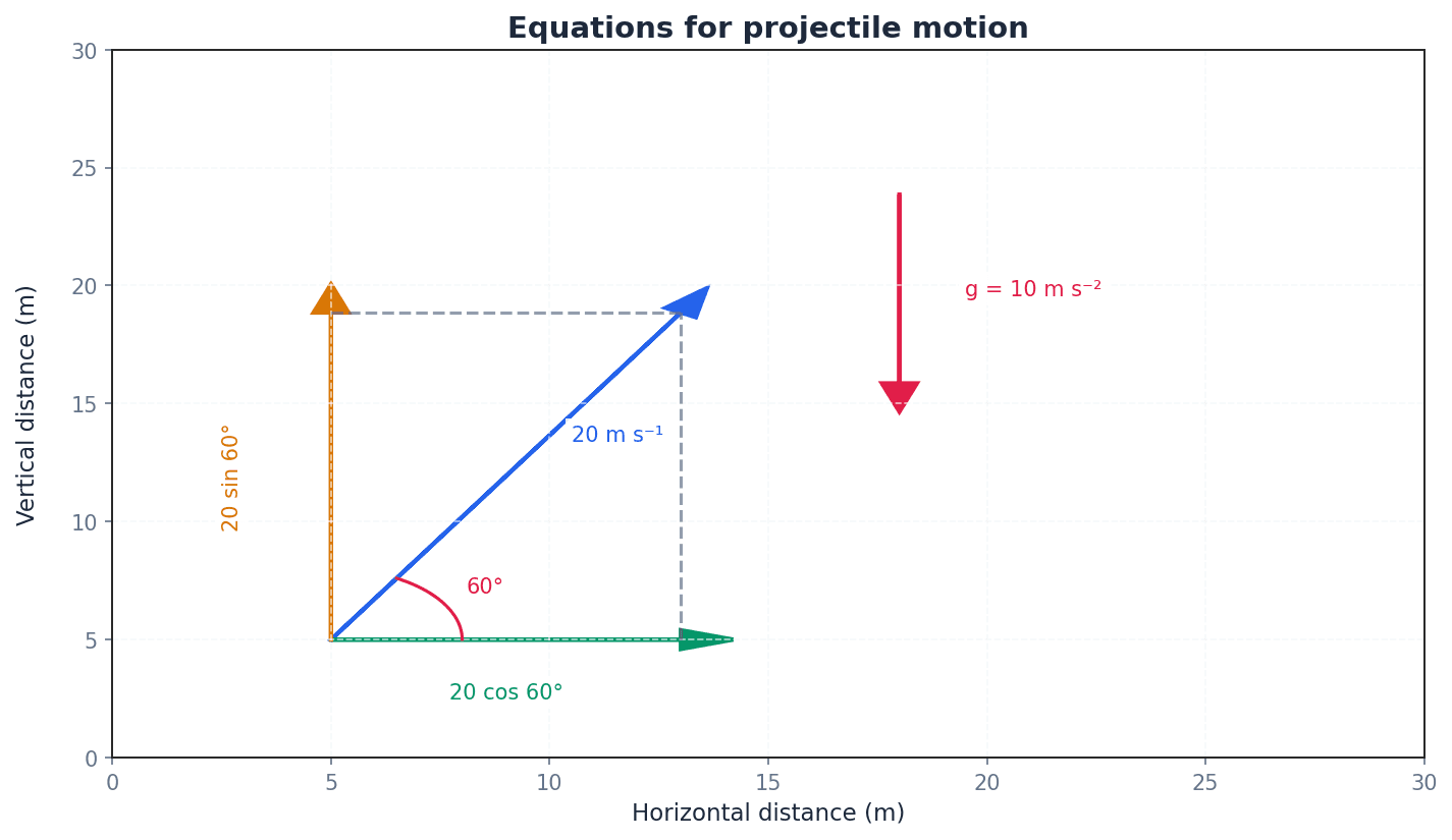
Projectile motion is analyzed by separating it into two independent components: horizontal and vertical. The initial velocity is resolved into its horizontal (u cos α) and vertical (u sin α) components. The horizontal motion is characterized by constant velocity, as there is no horizontal acceleration. The vertical motion is subject to constant downward acceleration due to gravity (g).
Students often think the horizontal velocity changes during flight, but it remains constant if air resistance is ignored. Students often think there's a horizontal acceleration component, but actually, in ideal projectile motion, horizontal velocity is constant.
Ensure you correctly resolve the initial velocity into its horizontal (u cos α) and vertical (u sin α) components, paying attention to the angle given relative to the horizontal.
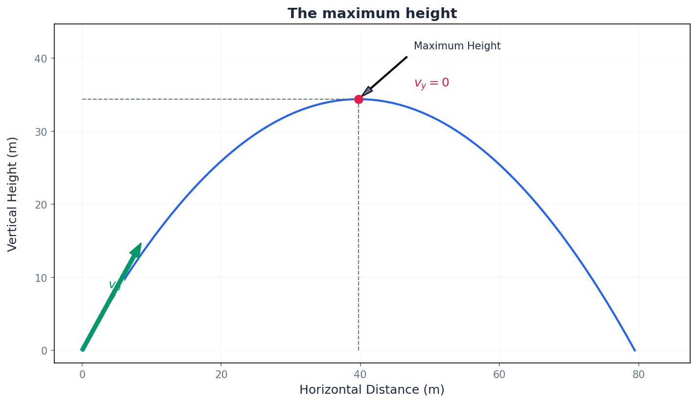
maximum height — The greatest vertical displacement reached by a projectile during its flight.
At this point, the vertical component of the projectile's velocity is zero. The horizontal velocity, however, remains constant. It's the highest point a ball reaches after being thrown upwards before it starts to fall back down.
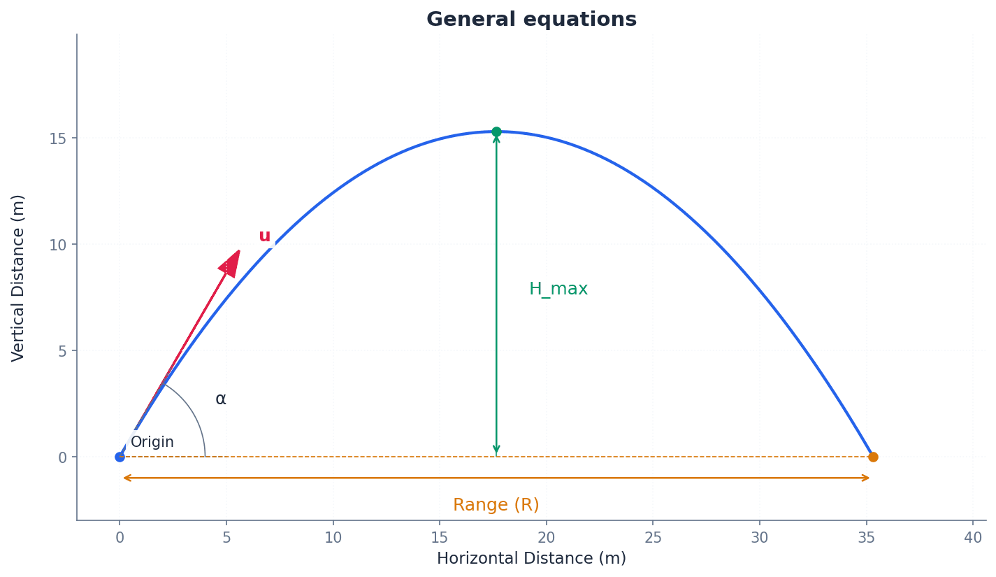
Maximum height (general)
For projection from horizontal ground.
Students often think the projectile stops completely at its maximum height, but only the vertical component of its velocity is zero. Students often think the projectile stops completely at maximum height, but actually only its vertical motion momentarily ceases; its horizontal motion continues.
Remember that at the maximum height, the vertical component of velocity (vᵧ) is momentarily zero, which is a key point for calculations.
time of flight — The total time a projectile spends in the air from projection until it lands.
This is typically found by setting the vertical displacement (y) to zero and solving for time, excluding the initial time t=0. For symmetrical paths, it's twice the time to reach maximum height. It's the duration from when a bird takes off until it lands again.
Time of flight (general)
For projection from horizontal ground, landing at the same level.
Students often think the time of flight is always twice the time to maximum height, but this is only true if the projectile lands at the same vertical level it was projected from.
When calculating time of flight, ensure you consider the initial and final vertical positions; if they are different, the symmetry assumption may not hold.
range — The total horizontal distance travelled by a projectile before it lands.
The range is calculated using the constant horizontal velocity and the total time of flight. It is maximized when the projection angle is 45 degrees for a given initial speed on level ground. It's how far a golf ball travels horizontally from the tee to where it first hits the ground.
Range (general)
For projection from horizontal ground, landing at the same level. Maximum at α = 45°.
Students often think maximum range is achieved at 90 degrees, but actually it's at 45 degrees on level ground.
To find the range, calculate the time of flight first, then multiply it by the constant horizontal velocity component.
height — The vertical displacement of a projectile from a reference point, usually the ground or the point of projection.
The height changes over time due to gravity, following a parabolic path. It is positive when above the reference and negative when below. It's how high a bird is flying above the ground.
Students often think height is always positive, but actually it can be negative if the projectile falls below its initial projection level.
Carefully define your origin and positive direction for vertical displacement (y) at the start of a problem to avoid sign errors.
The trajectory of a projectile is typically a parabola. This path can be described by an equation relating the vertical displacement (y) to the horizontal displacement (x), eliminating time (t). This general equation of trajectory is derived from the horizontal and vertical displacement equations and is useful for understanding the shape of the path without needing to consider time directly.
Equation of trajectory (y in terms of x)
For projection from origin (0,0) on horizontal ground. Can also be written as y = x tan α - (gx²/(2u²))(1 + tan² α).
Students often think the trajectory is a straight line if there's no air resistance, but actually gravity always causes a curved, parabolic path.
When asked to 'sketch the trajectory', ensure your drawing clearly shows a parabolic curve, not a straight line or an unrealistic path.
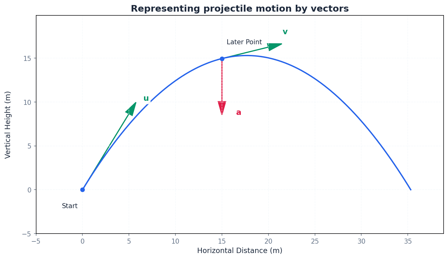
Projectile motion can also be analyzed using vector notation, which provides a more general approach for constant acceleration problems. The acceleration vector for a projectile is constant, given by α = (0, -g). The general vector equations for velocity and displacement can then be applied, where initial position and velocity are also expressed as vectors.
Vector form of velocity
General equation for constant acceleration.
Vector form of displacement
General equation for constant acceleration, where r - r₀ is displacement.
Students often confuse speed and velocity, forgetting that velocity is a vector quantity including direction. When asked for 'speed', calculate the magnitude of the velocity vector (√(vₓ² + vᵧ²)); when asked for 'velocity', provide both magnitude and direction (angle).
Always remember to use g (usually 9.8 or 10 m s⁻²) for vertical acceleration and 0 for horizontal acceleration in calculations, unless otherwise specified.
Always start by resolving the initial velocity (u) at an angle (α) into horizontal (u cos α) and vertical (u sin α) components.
Draw a large, clear diagram. Label the initial velocity, angle, and key points (start, max height, end).
Set up two columns for your suvat variables: one for horizontal motion (a=0) and one for vertical motion (a=-g). This prevents mixing up components.
Exam Technique
Calculating maximum height
Calculating time of flight (level ground)
| Mistake | Fix |
|---|---|
| Forgetting that horizontal velocity is constant throughout the flight. | Remember that in ideal projectile motion (no air resistance), there are no horizontal forces, so horizontal acceleration is zero, and thus horizontal velocity remains constant. |
| Thinking the projectile stops completely at its maximum height. | Only the vertical component of velocity is zero at maximum height. The horizontal motion continues, so the projectile still has a horizontal speed. |
| Using standard formulas for Range (R) or Time of Flight (T) when the projectile lands at a different height from its starting point. | These simplified formulas (e.g., R = u² sin(2α)/g) are only valid for projection from and landing on horizontal ground at the same level. For uneven ground, you must use the component-wise displacement equations and solve for t or x directly. |
This chapter introduces moments of forces, which quantify the turning effect of a force about a point. It explains the rigid body model, defines a couple, and expands the conditions for equilibrium to include both zero resultant force and zero resultant moment, enabling the analysis of static systems.
rigid body model — A model in which an object is recognised as having size and shape, but is assumed not to be deformed when forces act on it.
This model is necessary when forces do not all act through the same point, and turning effects are important. It allows for the analysis of rotation and equilibrium in extended objects, unlike the particle model. Think of a solid wooden plank; when you push it, it moves or turns as a whole without bending or breaking, which is how a rigid body behaves.
Students often think the particle model is always sufficient, but for turning effects, the rigid body model is essential because forces can act at different points.
moment of the force — The product of a force and its perpendicular distance from a fixed point.
This product quantifies the turning effect of a force about a specific point. A larger moment indicates a greater tendency to cause rotation. The direction of rotation (clockwise or anticlockwise) is also important. Imagine trying to open a door; pushing further from the hinges (increasing the perpendicular distance) with the same force makes it easier to open, demonstrating a larger moment.
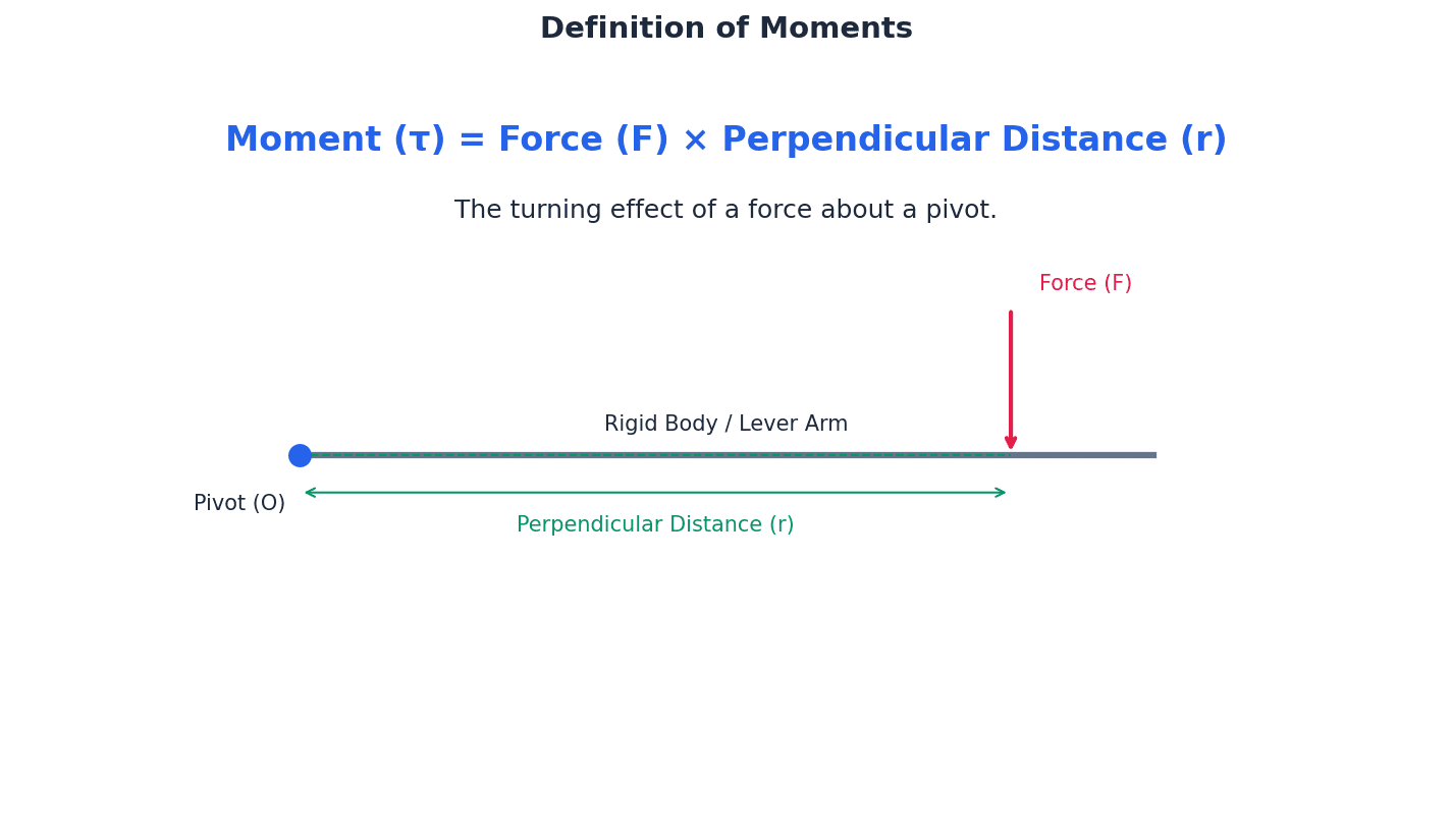
Moment of a force
d must be the perpendicular distance from the point O to the line of action of the force. Anticlockwise moments are typically considered positive, and clockwise moments are negative.
Students often think moment is just force times any distance, but it's actually force times the perpendicular distance from the point to the line of action of the force.
Always specify the point about which moments are taken. Failure to do so can lead to loss of marks, especially in equilibrium problems.
Moment of a force at an angle
Here, d is the distance from point O to the point of application of the force, and \alpha is the angle between the force vector and the line connecting O to the point of application. Alternatively, resolve F into components perpendicular and parallel to the line connecting O to the point of application; the moment is then F_perpendicular \times d.
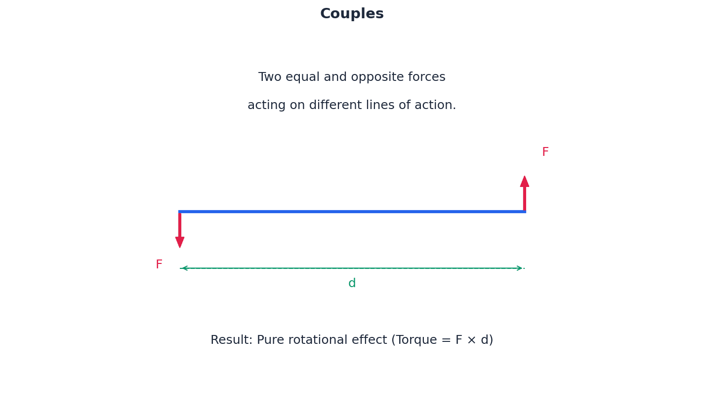
couple — Any set of forces with a zero resultant force but a non-zero total moment.
A couple consists of two forces of the same magnitude acting in opposite directions along different lines. It produces a pure turning effect (rotation) without any translational motion. The moment of a couple is the same about any point. Turning a steering wheel with both hands is an example of a couple; your hands apply equal and opposite forces on different sides, causing the wheel to rotate without moving sideways.
Students often think a couple has a resultant force, but its resultant force is zero; it only produces a turning effect.
Be careful to distinguish between a single force producing a moment and a couple. A couple's moment is constant regardless of the pivot point chosen.
equilibrium — A state where both the resultant force and the total moment on an object are zero, causing it to remain at rest or move at constant velocity.
For an object to be in complete equilibrium, it must not be accelerating translationally (resultant force is zero) and it must not be accelerating rotationally (resultant moment is zero). This ensures both linear and rotational stability. A book resting motionless on a table is in equilibrium; the upward normal force balances its weight (zero resultant force), and there are no turning forces acting on it (zero resultant moment).
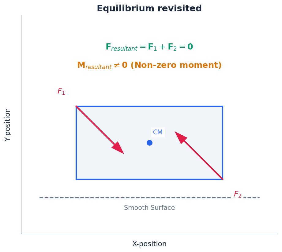
Students often think equilibrium only means zero resultant force, but it also requires the resultant moment about any point to be zero.
When solving equilibrium problems, always state both conditions: resultant force is zero AND resultant moment about any point is zero. Choose a pivot point strategically to simplify calculations (e.g., through an unknown force).
Levers are simple machines that depend on moments to amplify force or change the direction of motion. The effectiveness of a lever is determined by the distances of the applied force and the load from the fulcrum. By strategically placing the fulcrum, a smaller input force can generate a larger output force, or vice versa.
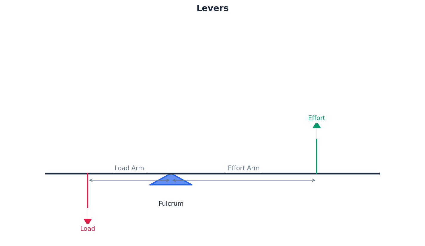
fulcrum — The pivot point about which a lever or other object turns.
The fulcrum is the fixed point that allows a lever to amplify force or change the direction of motion. The effectiveness of a lever depends on the distances of the applied force and the load from the fulcrum. On a see-saw, the central support is the fulcrum; it's the point around which the plank rotates.
Students often think the fulcrum is always at the center, but it can be positioned anywhere along the lever, influencing its mechanical advantage.
When calculating moments for levers, always take moments about the fulcrum to simplify the problem, as the force at the fulcrum will have zero moment about itself.
freely hinged — A hinge that is well oiled and has negligible friction between its inner and outer parts, meaning it cannot exert any moment.
A freely hinged connection allows rotation but does not resist it with a turning force. While it can exert reaction forces in any direction, it cannot produce a moment about the hinge point itself. Imagine a door hinge that is perfectly smooth and silent; it allows the door to swing without any resistance from the hinge itself. The hinge only supports the door's weight and any pushes/pulls.
Students often think a hinge cannot exert any force, but a freely hinged connection can exert reaction forces, just not a moment.
When a problem states 'freely hinged', remember that the moment about the hinge point due to the hinge's reaction force is zero, simplifying moment calculations.
Always draw a large, clear force diagram, labelling all forces (weight, reactions, tensions) and all relevant distances. When taking moments, strategically choose a pivot point where an unknown or unwanted force acts. The moment of that force about that point is zero, simplifying the equation. For equilibrium problems, set up separate equations for force equilibrium (e.g., resolving vertically and horizontally) and moment equilibrium. You often need to solve these simultaneously. Be consistent with your sign convention for moments (e.g., 'Anti-clockwise is positive') and state it clearly in your working.
Exam Technique
Calculating the moment of a single force
Solving equilibrium problems (static systems)
| Mistake | Fix |
|---|---|
| Using the distance along the object instead of the perpendicular distance from the pivot to the line of action of the force. | Always ensure 'd' in M=Fd is the shortest distance from the pivot to the line along which the force acts. If the force is at an angle, use trigonometry to find this perpendicular distance or resolve the force. |
| Forgetting to include the weight of the object (acting at its centre of mass) or a reaction force in the moment calculation. | Draw a comprehensive force diagram first, identifying ALL forces acting on the object, including its weight (usually at the geometric centre for uniform objects) and any reaction forces from supports or hinges. |
| Assuming equilibrium only requires the sum of forces to be zero, and forgetting that the sum of moments must also be zero. | Always state and apply both conditions for equilibrium: resultant force = 0 AND resultant moment = 0. This is crucial for rotational stability. |
This chapter defines the centre of mass for various body models and provides methods for its calculation in one, two, and three dimensions. It also explores the critical conditions under which an object will slide or topple, applying principles of moments and forces.
Centre of mass — The single point at which the whole mass of the body may be taken to be situated (particle model) or the balance point of a body with size and shape (rigid body model).
The centre of mass is a crucial concept for understanding how objects balance and move. For a system of particles, it's the weighted average of their positions. For extended bodies, it's the point where the entire weight can be considered to act, simplifying force and moment calculations. Imagine trying to balance a complex sculpture on a single finger; the point where it perfectly balances is its centre of mass.
Students often think the centre of mass must always be inside the physical body, but it can actually be outside, for example, in a hollow ring.
When asked to define centre of mass, ensure you mention both the particle model and rigid body model definitions for full marks. For calculations, clearly state your chosen origin.
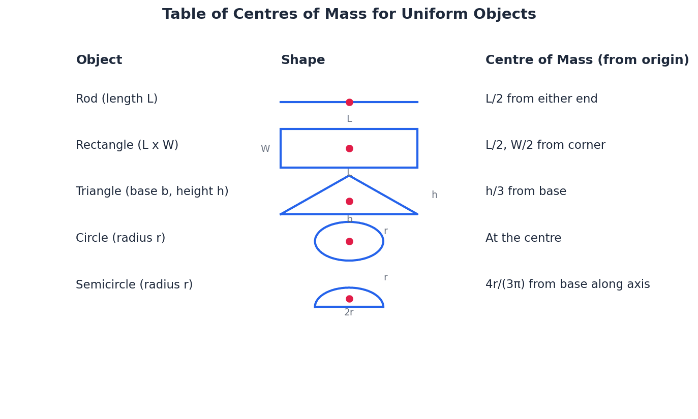
Median of a triangle — A line segment joining a vertex of a triangle to the mid-point of the opposite side.
In the context of finding the centre of mass of a triangular lamina, the centre of mass lies on each of the three medians. The intersection point of these medians is the centroid, which is the centre of mass for a uniform triangular lamina. Imagine balancing a triangular piece of cardboard; if you draw lines from each corner to the middle of the opposite side, where those lines cross is where it will balance.
Centroid — The intersection point of the three medians of a triangle, which is also the centre of mass for a uniform triangular lamina.
The centroid is a geometric property of a triangle. For a uniform triangular lamina, its physical centre of mass coincides with its centroid. This point is located 2/3 of the way from each vertex along the median to the midpoint of the opposite side. If you were to spin a perfectly balanced triangular plate on a pin, the pin would be placed exactly at the centroid.
Students often think the centre of mass of a triangle is at the average of the vertices' coordinates, but it's actually the intersection of the medians, which is 2/3 of the way along each median from the vertex.
When dealing with triangular laminae, remember that the centre of mass is at the centroid, which is 2/3 of the distance along the median from the vertex.
Centre of mass (1D)
Used for a set of point masses or composite bodies along a single axis, where the origin O is chosen as a reference point.
Centre of mass (2D)
Used for a set of point masses or composite bodies in a two-dimensional plane, where (x_i, y_i) are the coordinates of each mass.
Centre of mass (3D)
Used for a set of point masses or composite bodies in three dimensions, where (x_i, y_i, z_i) are the coordinates of each mass.
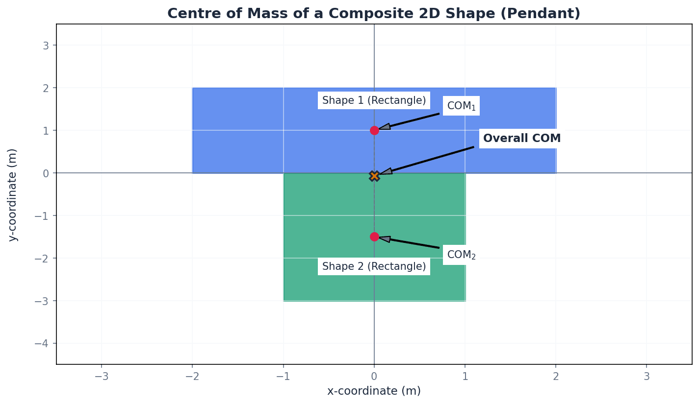
The position of the centre of mass for a system of point masses or composite bodies can be calculated in one, two, or three dimensions. This involves summing the moments of individual masses about a chosen origin and equating it to the moment of the total mass acting at the centre of mass. For composite bodies, each component is treated as a point mass located at its own centre of mass. When a body has a hole, the removed part is treated as having a negative mass in the calculation.
Students might forget to include the mass of the object itself when calculating the centre of mass for composite bodies, or confuse the centre of mass with the geometric centre, especially for non-uniform or asymmetric objects.
Always define a clear origin and coordinate axes at the start of a Centre of Mass calculation. Use a table to organise the mass, x-coordinate, and y-coordinate for each component of a composite body to minimise errors.
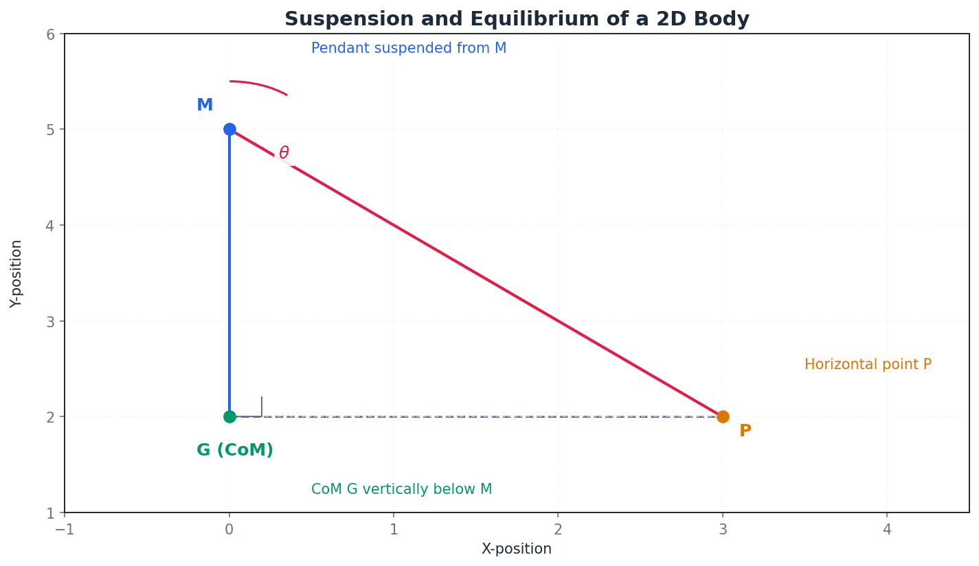
When a two-dimensional body is freely suspended from a point, it will come to rest in equilibrium such that its centre of mass hangs vertically below the point of suspension. This principle allows for the determination of the centre of mass by suspending the object from multiple points and finding the intersection of the vertical lines. Conversely, to achieve a specific orientation, the suspension point must be adjusted so that it lies directly above the desired centre of mass position.
Sliding — The motion of an object across a surface when the applied force parallel to the surface exceeds the maximum static friction.
Sliding occurs when the tangential force applied to an object overcomes the frictional resistance between the object and the surface it rests on. The condition for sliding is typically F > µR, where F is the applied tangential force, µ is the coefficient of friction, and R is the normal reaction force. Imagine pushing a heavy box across the floor; if you push hard enough, it will slide.
When analysing sliding, remember to resolve forces parallel and perpendicular to the surface. The critical condition for sliding is F = µR.
Toppling — The rotation of an object about an edge or pivot point, leading to it falling over, which occurs when the line of action of its weight falls outside its base of support.
Toppling happens when the moment created by the weight of an object about its pivot edge exceeds any opposing moments, causing it to rotate and fall. The critical condition for toppling is when the centre of mass is directly above the pivot edge. Imagine pushing over a tall, narrow wardrobe; it will eventually tip over rather than slide if the base is wide enough or friction is high.
Students often think sliding always happens before toppling, or vice versa, without considering the specific conditions. It depends on the object's dimensions, the point of force application, and the coefficient of friction.
For toppling problems, take moments about the pivot edge. The normal reaction and friction forces act through this pivot at the point of toppling, so their moments are zero about this point.
Students often think toppling is only about the height of the centre of mass, but the width of the base of support is equally important. Also, students may incorrectly identify the pivot point when calculating moments for toppling problems.
To determine whether an object will slide or topple first when subjected to an increasing force, the critical force (or angle) required for each event must be calculated. The event that requires the smaller force (or is reached at a smaller angle) will occur first. Sliding is governed by the coefficient of friction and the normal reaction force, while toppling is determined by the moments created by the weight and the applied force about the potential pivot point.
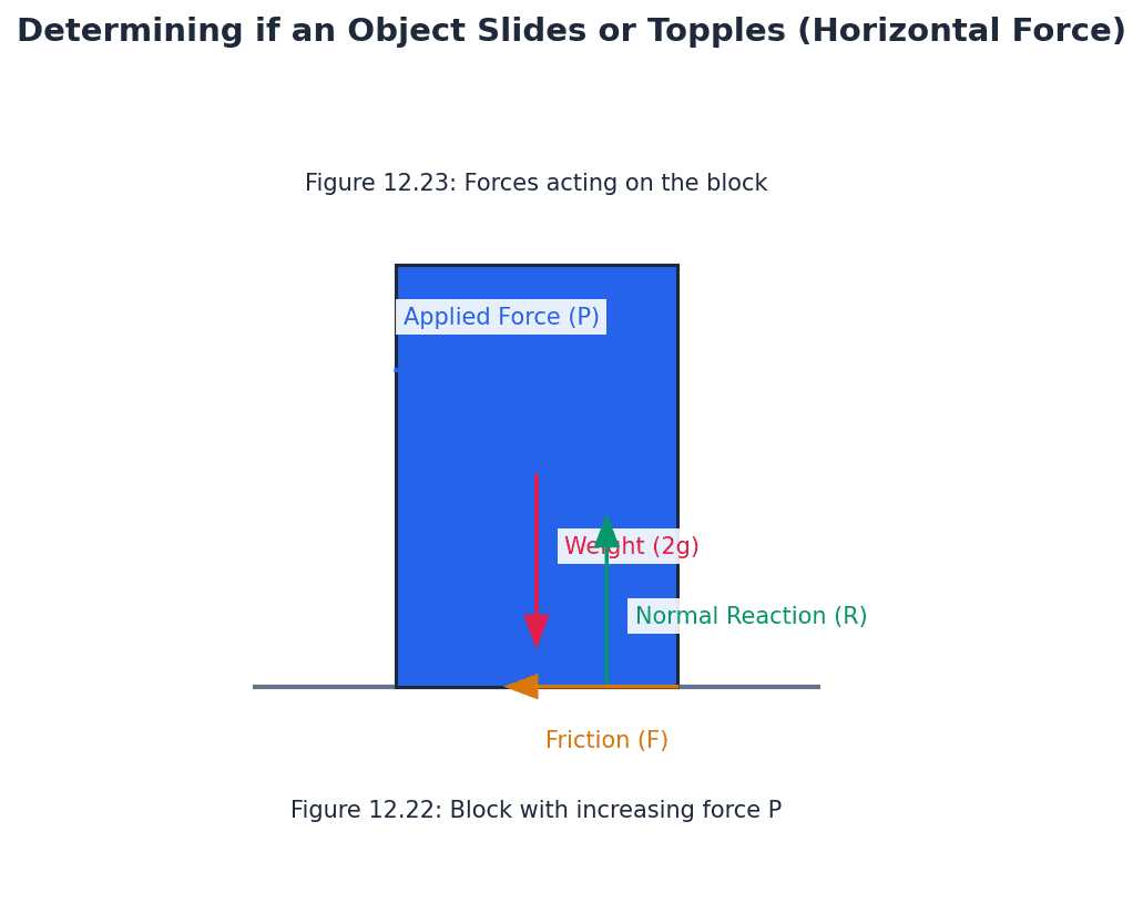
To determine if an object slides or topples first, calculate the force (or angle) required for each to occur. The smaller value dictates the initial event. Draw large, clear diagrams for equilibrium problems, marking the CoM, weight, reaction force, friction, and the potential pivot point.
Exam Technique
Calculating Centre of Mass for Point Masses/Composite Bodies (1D, 2D, 3D)
Calculating Centre of Mass for a Body with a Hole
| Mistake | Fix |
|---|---|
| Assuming the centre of mass is always inside the physical body. | Remember that for objects like hollow rings, the centre of mass can be located outside the material of the body itself. |
| Confusing the centre of mass with the geometric centre, especially for non-uniform or asymmetric objects. | The centre of mass is a weighted average of mass distribution, not just the geometric midpoint. Always use the formula M \bar{r} = \sum m_i r_i. |
| Forgetting to include the mass of the original shape when calculating the centre of mass of a composite body, or incorrectly handling 'negative mass' for holes. | Ensure all components, including the main body and any added/removed parts, are accounted for in the total mass and moment calculations. For holes, treat the removed part as having a negative mass. |
This chapter explores uniform motion in a circle, where an object moves at a constant speed but continuously accelerates due to its changing direction. It introduces angular speed and centripetal force, explaining how various physical forces provide the necessary inward acceleration to maintain circular motion.
angular speed — The rate at which the angle θ is increasing, or the rate at which the position vector is rotating.
Angular speed, denoted by ω, measures how fast an object rotates or revolves around a central point, typically measured in radians per second. It is a scalar quantity in this context. Imagine a merry-go-round; everyone on it has the same angular speed, but people further from the centre are moving faster linearly.
Students often think angular speed is the same as linear speed, but actually angular speed is the rate of change of angle, while linear speed is the rate of change of distance along the arc.
radial direction — The direction along the radius, either towards or away from the centre of the circle.
In circular motion, components of velocity and acceleration are often resolved into radial and transverse directions. The positive radial direction is typically taken as outwards from the centre. If you're standing in the middle of a clock face, the radial direction is along any of the hands pointing outwards from the centre.
transverse direction — The direction at right angles to the radius, tangential to the circular path.
This direction is perpendicular to the radial direction and is along the tangent to the circle at the particle's position. The linear velocity of a particle in circular motion is always in the transverse direction. If you're driving a car around a circular track, the transverse direction is the direction your car is actually moving at any instant.
Students often confuse radial and transverse directions, but actually radial is along the radius, while transverse is perpendicular to it (tangential).
Arc length
θ must be in radians.
Linear speed from angular speed
ω must be in radians per second.
Always ensure angles are in radians when using formulas relating linear and angular speed (v = rω) and acceleration (a = rω²), as this is a common error.
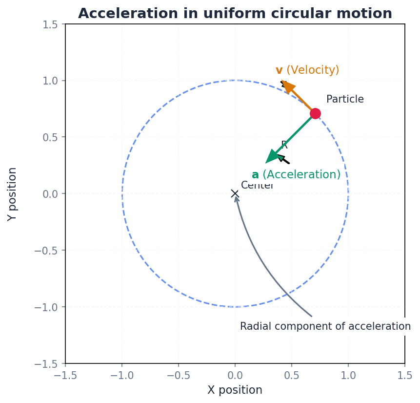
Even when an object moves at a constant speed in a circular path, its velocity is continuously changing because its direction is constantly altering. This change in velocity signifies that the object is accelerating. This acceleration, known as centripetal acceleration, is always directed towards the centre of the circular path.
Students often think that an object moving at constant speed in a circle has no acceleration, but actually its velocity is constantly changing due to direction change, meaning it is accelerating.
Radial component of velocity
For a circle, r is constant, so this component is 0.
Transverse component of velocity
This is the linear speed v.
Radial component of acceleration
Directed towards the centre of the circle (negative sign indicates towards centre if positive radial is outwards).
Transverse component of acceleration
Zero for uniform circular motion (constant angular speed).
Students often think transverse acceleration is always zero in circular motion, but actually it is only zero for uniform circular motion (constant angular speed); if angular speed changes, there is transverse acceleration.
Magnitude of centripetal acceleration (using angular speed)
Directed towards the centre of the circle.
Magnitude of centripetal acceleration (using linear speed)
Directed towards the centre of the circle.
centripetal force — A force towards the centre of a circular path, necessary for a particle to move in that path.
According to Newton's first law, an object moving in a circle must be acted upon by a resultant force towards the centre to produce the required centripetal acceleration. This force is not a new type of force but rather the net force provided by other forces like tension, friction, or gravity. When you swing a ball on a string, the tension in the string is the centripetal force pulling the ball towards your hand, keeping it in a circle.
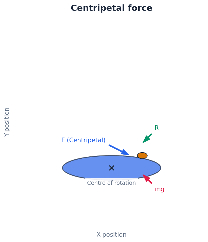
Students often think centripetal force is a separate force that appears, but actually it is the name given to the resultant force (e.g., friction, tension, gravity) that causes circular motion.
When solving problems, identify the specific physical force(s) providing the centripetal force (e.g., friction, tension, normal reaction, gravity) and resolve them towards the centre of the circle.
Centripetal force (using angular speed)
This is the resultant force towards the centre.
Centripetal force (using linear speed)
This is the resultant force towards the centre.
Newton's second law is fundamental to understanding circular motion. The resultant force acting on an object moving in a circle must be equal to its mass times its centripetal acceleration. This resultant force is the centripetal force, and it is always directed towards the centre of the circle. By resolving forces into radial and transverse components, problems involving centripetal force can be solved in various contexts.
conical pendulum — A system where a bob tied to a string rotates in a horizontal circle below a fixed point, with the string describing a cone.
In a conical pendulum, the tension in the string and the weight of the bob provide the necessary forces. The horizontal component of tension provides the centripetal force, while the vertical component balances the weight. Imagine a child on a swing, but instead of swinging back and forth, they are pushed to move in a horizontal circle, with the chains forming a cone.
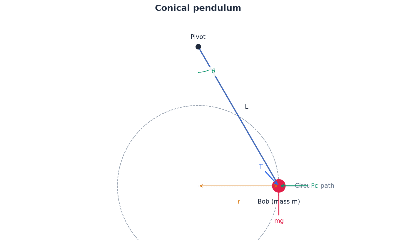
Students often think the string in a conical pendulum can be horizontal, but actually the string must have a vertical component of tension to balance the weight of the bob, so it can never be perfectly horizontal.
When analyzing a conical pendulum, resolve the tension force into horizontal (centripetal) and vertical (balancing weight) components; the angle with the vertical is crucial.
Conical pendulum angle relation
Derived from resolving forces vertically and horizontally.
banked tracks — Roads or railway tracks that are tilted so that the outer edge of a bend is higher than the inner edge.
Banking allows a component of the normal reaction force to provide some or all of the necessary centripetal force, reducing or eliminating the reliance on friction, especially at a specific 'ideal' speed. Think of a velodrome cycling track, where the bends are steeply angled to allow cyclists to take corners at high speeds without skidding.
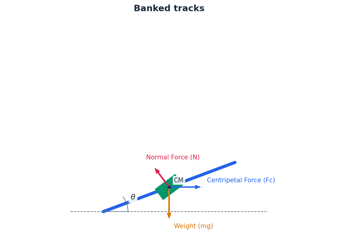
Students often assume that banking a track eliminates friction entirely, but actually it only eliminates the need for friction at a specific ideal speed; friction still acts at other speeds.
For banked tracks, resolve the normal reaction force into horizontal and vertical components. The horizontal component contributes to the centripetal force, and the vertical component helps balance the weight.
Banked track ideal speed
Speed at which no frictional force is required to prevent slipping.
The principles of uniform circular motion also apply to orbital motion, such as satellites orbiting a planet. In these cases, the gravitational force between the satellite and the central body provides the necessary centripetal force, keeping the satellite in its circular path. This allows for the determination of orbital speeds and periods.
Always start with a large, clear force diagram. Label all real forces acting on the particle (Weight, Tension, Normal Reaction, Friction).
Apply Newton's Second Law by resolving forces. The most common method is resolving horizontally (towards the centre) and vertically.
When a question asks for a maximum or minimum speed on a bend, this is a signal that a limiting force, usually friction (F ≤ μR), is involved.
Exam Technique
Calculating angular/linear speed and acceleration on a turntable
Determining when an object on a turntable will slide
| Mistake | Fix |
|---|---|
| Confusing centripetal force with a new type of force. | Remember that centripetal force is the *resultant* of existing physical forces (e.g., friction, tension, gravity) acting towards the centre. It is not drawn as a separate force on a free-body diagram. |
| Assuming constant speed means zero acceleration. | Velocity is a vector quantity, meaning it has both magnitude (speed) and direction. In circular motion, even if speed is constant, the direction is continuously changing, hence there is always an acceleration (centripetal acceleration). |
| Failing to convert angular speeds to radians per second. | Always convert units like revolutions per minute (rpm) or degrees per second into radians per second (rad s⁻¹) before using formulas such as v = rω or a = rω². |
This chapter introduces Hooke's law, which describes the proportional relationship between the tension or thrust in an elastic material and its extension or compression. It defines key terms, explores different forms of Hooke's law, and develops the concept of elastic potential energy. The chapter also demonstrates the application of the principle of conservation of energy in mechanical systems involving elastic materials.
inextensible — Strings that do not stretch when they are under tension are called inextensible.
This is an ideal modelling assumption often used in mechanics problems where the stretching of a string is negligible. In reality, all materials stretch to some extent, but for practical purposes, some materials can be considered inextensible, like a steel cable used to lift heavy machinery.
Students often think inextensible means 'unbreakable', but actually it only means 'does not stretch' under tension, not that it can withstand infinite force.
elastic — Strings and springs which stretch are said to be elastic.
Elastic materials return to their original length once the deforming force is removed, provided they have not exceeded their elastic limit. This property is crucial for applications like bungee ropes and springs, much like a rubber band returning to its original shape after being stretched.
Students often think 'elastic' means 'stretchy' without limit, but actually it implies the ability to return to the original shape, and there's an 'elastic limit' beyond which permanent deformation occurs.
open coiled springs — Open coiled springs are springs which can also be compressed.
Unlike some strings or closed-coil springs, open coiled springs can exert both tension when stretched and thrust when compressed, making them versatile for various mechanical applications. The springs in a car's suspension are open coiled; they compress when the car goes over a bump and extend when the car lifts.
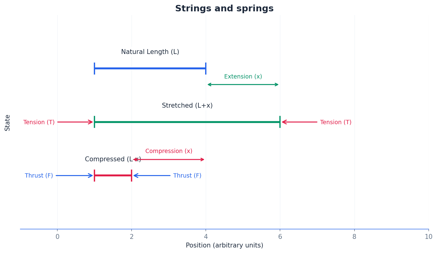
natural length — The length of a string or spring when there is no force applied to it is called its natural length.
This is the equilibrium length of the elastic material before any external forces cause it to stretch or compress. It is a fundamental property used in Hooke's law calculations, similar to the length of a relaxed rubber band before it is pulled.
Always identify the natural length (l₀) at the start of a problem, as extension (x) is measured relative to this value.
extension — If it is stretched, the increase in length is called its extension.
Extension is the positive change in length from the natural length when a tensile force is applied. It is a key variable in Hooke's law and elastic potential energy calculations. For example, if a spring is 10 cm long at rest and stretched to 12 cm, its extension is 2 cm.
Students often confuse extension with the total length of the string/spring; extension is the *change* in length from the natural length.
compression — If a spring is compressed it is said to have a negative extension or compression.
Compression is the decrease in length from the natural length when a compressive force (thrust) is applied. It is treated as a negative extension in Hooke's law, where the force becomes a thrust. For instance, if a spring is 10 cm long at rest and pushed to 8 cm, its compression is 2 cm (or an extension of -2 cm).
Students often think compression is a different phenomenon from extension, but actually it's mathematically treated as a negative extension in Hooke's law, leading to a thrust.
tension — When stretched, a spring exerts an inward force, or tension, on whatever is attached to its ends.
Tension is a pulling force transmitted axially by a string or spring. It acts inwards along the length, trying to restore it to its natural length, much like the force felt pulling back on your hands when you pull a rope.
thrust — When compressed it exerts an outward force, or thrust, on its ends.
Thrust is a pushing force exerted by a compressed spring, acting outwards from its ends. It is the compressive equivalent of tension and is also proportional to the compression according to Hooke's law, similar to the force a spring pushes back with when you push down on it.
Hooke's law describes the fundamental behavior of elastic materials. It states that the tension or thrust in an elastic string or spring is directly proportional to its extension or compression, respectively. This linear relationship holds true for materials that are 'perfectly elastic', meaning they return to their original length without permanent deformation when the deforming force is removed, provided they have not exceeded their elastic limit.
perfectly elastic — Strings or springs which exhibit this linear behaviour are said to be perfectly elastic.
A perfectly elastic material obeys Hooke's law, meaning the tension/thrust is directly proportional to the extension/compression, and it returns to its original length without any permanent deformation when the load is removed, within its elastic limit. This is like an ideal spring in physics problems, always returning to its exact natural length.
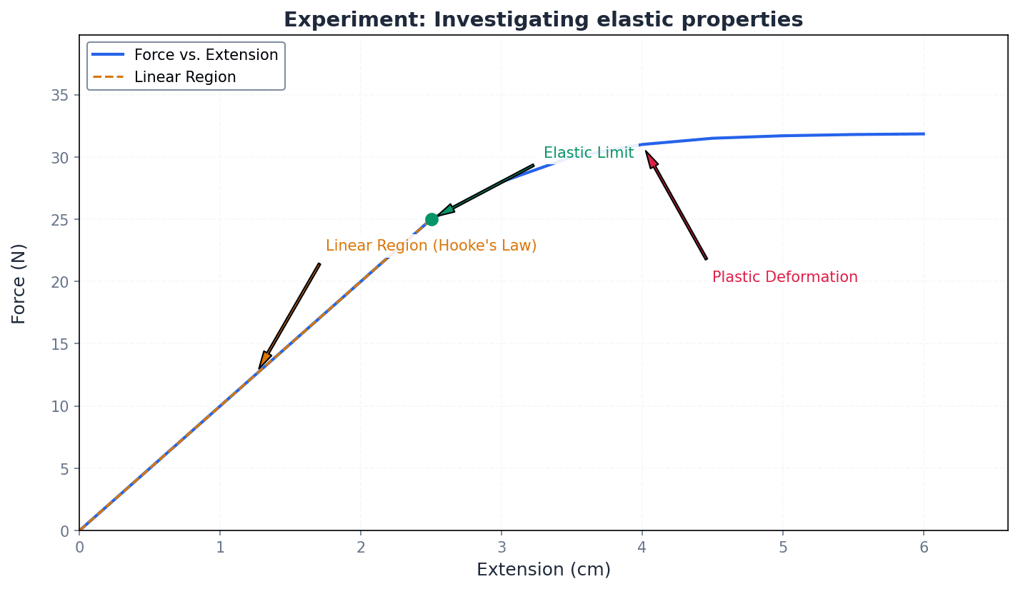
elastic limit — If you kept increasing the weight, the string or spring might have stopped stretching or might have stretched without returning to its original length. In this case the graph would no longer be a straight line: the material had passed its elastic limit.
The elastic limit is the maximum stress or force a material can withstand without undergoing permanent deformation. Beyond this point, the material will not return to its natural length when the load is removed, and Hooke's law no longer applies linearly. If you stretch a rubber band too far, it might not snap back to its original size, or it might even break; that point where it stops returning is its elastic limit.
Students may assume Hooke's law applies indefinitely, forgetting about the elastic limit beyond which the material deforms permanently or breaks.
Hooke's law can be expressed in several forms, each useful in different contexts. These forms relate tension (T) to extension (x) and incorporate properties of the material or the specific object. Understanding these distinctions is crucial for applying the law correctly in various problems.
Hooke's Law (Young Modulus form)
Used in physics and engineering; E is a material property, A is the cross-sectional area, and l₀ is the natural length.
Young modulus — In this form E is called the Young modulus and is a property of the material out of which the string is formed.
The Young modulus (E) is a measure of the stiffness of an elastic material, defined as the ratio of stress to strain. It is an intrinsic property of the material itself, independent of the dimensions of the string or spring. For example, steel has a much higher Young modulus than rubber because it's much harder to stretch.
Hooke's Law (Modulus of Elasticity form)
Commonly used in this book; λ is a property of the string/spring for a given cross-section and material, and l₀ is the natural length.
modulus of elasticity — The constant λ is called the modulus of elasticity of the string and will be the same for any string of a given cross-section made out of the same material.
The modulus of elasticity (λ) is a constant specific to a particular elastic string or spring, incorporating both the material's Young modulus and the string's cross-sectional area. It is used in the form T = λx/l₀ and is commonly used in mathematics problems. Think of it as a 'customized' stiffness for a specific piece of elastic material.
This is the preferred form in this textbook (T = λx/l₀). Ensure you use the correct natural length (l₀) in the denominator and that λ has units of N.
Students often confuse modulus of elasticity (λ) with Young modulus (E), but actually λ is E multiplied by the cross-sectional area (A), making it a property of the specific string, not just the material.
Hooke's Law (Stiffness form)
Simplest form when natural length and cross-sectional area are not relevant; k is a property of the string/spring as a whole.
stiffness — In this simplest form, k is called the stiffness of the string.
Stiffness (k) is a property of the string or spring as a whole, representing the force required to produce a unit extension. It is the gradient of the force-extension graph. A very stiff spring requires a lot of force to stretch it a little bit, like a car suspension spring.
Relationship between stiffness and modulus of elasticity
Connects the stiffness constant to the modulus of elasticity and natural length.
Students often confuse Young modulus (E), modulus of elasticity (λ), and stiffness (k), which are related but distinct properties (material vs. object specific).
Students sometimes use the total length instead of the natural length (l₀) in the denominator of Hooke's law (T = λx/l₀) or the elastic potential energy formula (E.P.E. = λx²/2l₀).
When an elastic string or spring is stretched or compressed, work is done against the internal forces. This work is stored as elastic potential energy within the material. Since the tensions and thrusts in perfectly elastic materials are conservative forces, this stored energy can be fully recovered, often converting into kinetic or gravitational potential energy in mechanical systems.
conservative forces — The tensions and thrusts in perfectly elastic springs and strings are conservative forces, since any work done against them can be recovered in the form of kinetic energy.
A conservative force is one for which the work done in moving a particle between two points is independent of the path taken. For such forces, a potential energy can be defined, and mechanical energy is conserved in their presence. Gravity is a conservative force; the work done lifting an object to a certain height is the same regardless of the path.
elastic potential energy — The work done in stretching or compressing a string or spring can therefore be regarded as potential energy. It is known as elastic potential energy.
Elastic potential energy is the energy stored in an elastic material as a result of its deformation (stretching or compressing). This stored energy can be converted into other forms of energy, such as kinetic energy, when the material returns to its natural length. A stretched catapult stores elastic potential energy, which is then released to propel the projectile.
Work done by a variable force (integral form)
Used to calculate work done when force is not constant, by integrating force with respect to displacement.
Elastic Potential Energy
Energy stored in a stretched or compressed spring/string; also expressed as ½kx². x is the extension or compression from the natural length.
The formula E.P.E. = λx²/2l₀ (or ½kx²) is crucial. Remember that x is the extension (or compression) from the natural length, and it must be squared, so the sign of x doesn't matter for the energy value.
Students often think elastic potential energy is only stored when stretched, but actually it's also stored when a spring is compressed.
When calculating work done or energy stored for a change in extension (from x₁ to x₂), students might incorrectly use the difference (x₂ - x₁) in the E.P.E. formula, instead of calculating E.P.E. at x₂ and subtracting E.P.E. at x₁.
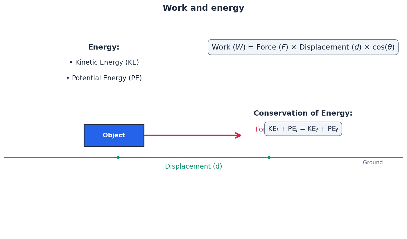
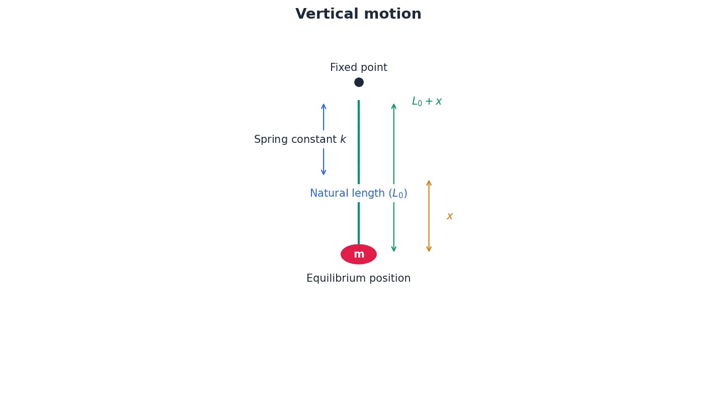
The principle of conservation of energy is a powerful tool for solving problems involving elastic materials, especially in vertical motion scenarios like bungee jumping. By equating the total mechanical energy (kinetic, gravitational potential, and elastic potential) at different points in a system's motion, unknown quantities such as speed or maximum extension can be determined. This approach is particularly useful when forces are variable, as is the case with elastic forces.
For dynamic problems (e.g., a falling mass or bungee), use the principle of Conservation of Energy. Compare the total energy (KE + GPE + EPE) at two different points in the motion.
When dealing with conservative forces like tension/thrust, you can use the principle of conservation of mechanical energy, equating changes in kinetic, gravitational potential, and elastic potential energies.
Always start by drawing a clear diagram. Label the natural length (l₀), the final length (L), and the extension (x).
For static equilibrium problems, resolve forces. For a vertically hanging mass, Tension = Weight, so (λ/l₀)x = mg.
When using conservation of energy, carefully define your zero level for Gravitational Potential Energy (GPE).
Remember that E.P.E. is zero only when the extension is zero (x=0), which is at the natural length.
Exam Technique
Equilibrium problems (static)
Dynamic problems (vertical motion, conservation of energy)
| Mistake | Fix |
|---|---|
| Confusing extension (x) with the total length (L) of the string/spring. | Always calculate extension as x = L - l₀, where l₀ is the natural length. |
| Using the total length (L) instead of the natural length (l₀) in the denominator of Hooke's law (T = λx/l₀) or the elastic potential energy formula (E.P.E. = λx²/2l₀). | The denominator in these formulas must always be the natural length (l₀). |
| Incorrectly calculating the change in E.P.E. for a change in extension. | The change from extension x₁ to x₂ is E.P.E.(x₂) - E.P.E.(x₁), NOT E.P.E.(x₂ - x₁). |
This chapter explores linear motion under variable forces, where Newton's second law is expressed as a differential equation. It demonstrates how calculus, specifically differentiation and integration, is crucial for solving these problems to determine velocity and displacement.
differential equation — An equation involving derivatives of a function, used to express Newton's second law for variable forces.
When the force acting on a body is not constant, its acceleration also varies. Newton's second law can then be written in a form that relates force to the rate of change of velocity or displacement, which is a differential equation. Solving this equation allows for the determination of velocity and displacement over time. Imagine trying to predict the path of a boat in a river where the current's speed changes constantly; a differential equation is like a mathematical rule describing how the boat's speed and direction change at every instant.
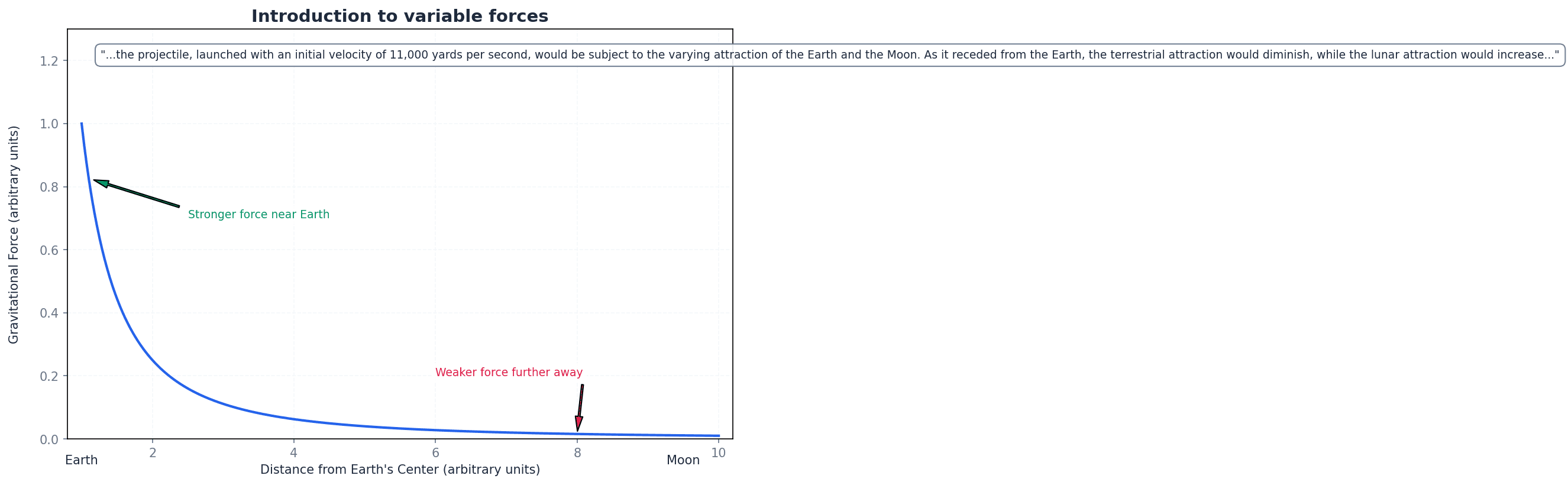
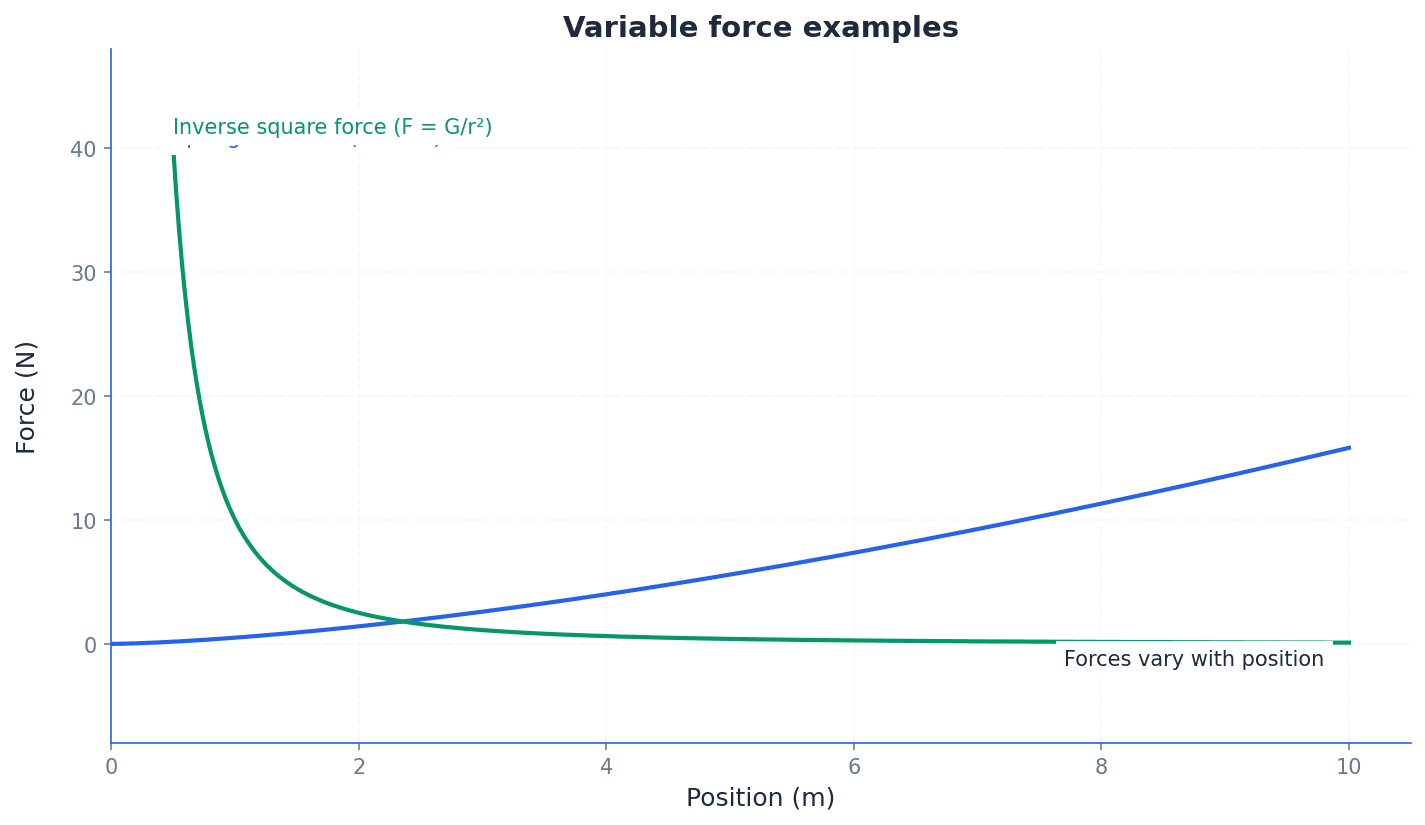
variable force — A force whose magnitude or direction changes continuously as motion proceeds.
Unlike constant forces, variable forces depend on factors like time, displacement, or velocity. Examples include gravitational attraction between celestial bodies, spring tension, and air resistance. Think of pushing a swing: if your push varies in strength and timing, the swing's motion becomes more complex, similar to motion under a variable force.
constant acceleration formulae — A set of equations (e.g., v = u + at, s = ut + ½at², v² = u² + 2as) used to describe motion when acceleration is uniform.
These formulae are derived from Newton's second law under the assumption of constant force and thus constant acceleration. They provide direct relationships between initial velocity, final velocity, acceleration, displacement, and time, but are not applicable when the force is variable. These formulae are like a set of shortcuts for a straight road with a constant speed limit; they work perfectly for that specific scenario.
kinetic energy — The energy possessed by an object due to its motion, given by the formula ½mv².
In problems involving variable forces, changes in kinetic energy can be found by integrating the force with respect to displacement. This is particularly useful when the force is a function of displacement, as the integral ∫F(s)ds directly relates to the change in ½mv². Kinetic energy is like the 'moving power' of an object; a faster or heavier object has more moving power.
Newton's Second Law (velocity-time form)
Used when force is a function of time or velocity, and time is the desired output.
Newton's Second Law (velocity-displacement form)
Used when force is a function of displacement or velocity, and displacement is the desired output.
When a force acting on a body is not constant, its magnitude or direction changes continuously throughout the motion. This means the acceleration of the body will also vary. Examples of variable forces include air resistance, which depends on velocity, and gravitational attraction over large distances, which depends on displacement.
For problems involving variable forces, Newton's second law, F=ma, must be expressed as a differential equation. This is because acceleration 'a' is no longer constant but is a derivative of velocity or displacement. The choice of acceleration form, dv/dt or vdv/ds, is crucial and depends on the nature of the variable force and the quantity being sought.
Identify whether the force is a function of time, displacement, or velocity, as this dictates which form of acceleration (dv/dt or vdv/ds) to use in Newton's second law.
Students often incorrectly apply constant acceleration formulae (suvat equations) to problems where the force, and thus acceleration, is variable. Remember that these formulae are only valid when acceleration is constant; for variable forces, calculus methods are required.
Solving problems with variable forces involves setting up Newton's second law as a differential equation and then using calculus techniques, specifically integration, to find expressions for velocity and displacement. The process typically involves separating variables and integrating both sides of the equation, using initial conditions to determine constants of integration.
When asked to 'write down a differential equation of motion', ensure you correctly substitute the given variable force into F=ma, using the appropriate form of acceleration (dv/dt or vdv/ds).
The form of the differential equation and the integration method depend on how the variable force is expressed. If the force is a function of time, F(t), use F = m(dv/dt). If the force is a function of displacement, F(s), use F = mv(dv/ds). If the force is a function of velocity, F(v), either form of acceleration can be used depending on whether time or displacement is required.
Students often confuse the choice of acceleration form (dv/dt or vdv/ds). Remember to select the correct form based on whether the force is a function of time, displacement, or velocity, and what quantity (time or displacement) is being sought.
Constant Acceleration Formula (velocity-time)
Derived from integrating F=m(dv/dt) when acceleration 'a' is constant.
Constant Acceleration Formula (displacement-time)
Derived from integrating v=u+at when acceleration 'a' is constant.
Constant Acceleration Formula (velocity-displacement)
Derived from integrating F=mv(dv/ds) when acceleration 'a' is constant.
The familiar constant acceleration formulae (often called 'suvat' equations) can be derived by integrating Newton's second law under the specific condition that acceleration 'a' is constant. For instance, integrating dv/dt = a with respect to time yields v = at + C, where C is the initial velocity 'u', giving v = u + at.
Never use constant acceleration formulae (suvat equations) in problems involving variable forces; always resort to setting up and solving differential equations.
When asked for 'loss of kinetic energy', ensure you calculate the difference between initial and final kinetic energy, and be careful with signs if the force is resistive.
Always draw a clear diagram and define a positive direction. This helps get the signs of forces correct in your F = ma setup, especially for resistive forces or gravity.
Exam Technique
Determine velocity and displacement when force is a function of time F(t)
Determine velocity and displacement when force is a function of displacement F(s)
| Mistake | Fix |
|---|---|
| Applying 'suvat' equations to problems with variable forces. | Always check if the force is constant. If it's variable, you must use calculus (differential equations) with F=m(dv/dt) or F=mv(dv/ds). |
| Choosing the incorrect form of acceleration (dv/dt vs vdv/ds). | If the force is a function of time F(t) or you need time, use dv/dt. If the force is a function of displacement F(s) or you need displacement, use vdv/ds. If F(v), choose based on whether time or displacement is required. |
| Making sign errors when setting up the F=ma equation. | Always draw a clear diagram and define a consistent positive direction. Ensure resistive forces oppose motion and gravitational forces act downwards (or in the negative direction if upward is positive). |
Generated by Nexelia Academy · nexeliaacademy.com